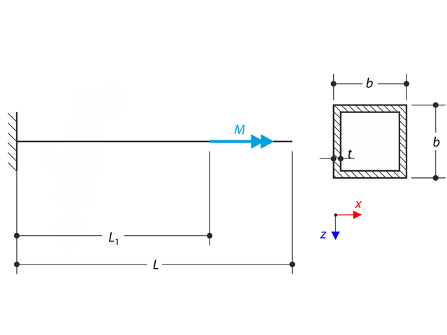
A thin-walled cantilever of a QRO-profile is fully fixed on the left end and warping is free. The cantilever is subjected to torque. Small deformations are considered, and the self-weight is neglected. Determine the maximum rotation, primary moment, secondary moment, and warping moment. The verification example is based on the example introduced by Gensichen and Lumpe.
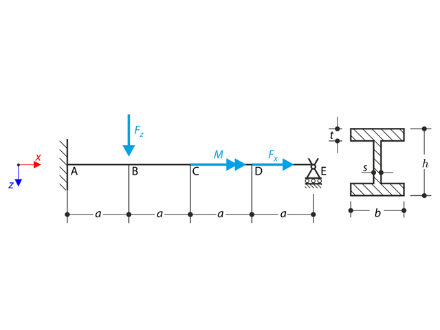
A beam is fully fixed (warping is restricted) on the left end and supported by a fork support (free warping) on the right end. The beam is subjected to a torque, longitudinal force, and transverse force. Determine the behavior of the primary torsional moment, secondary torsional moment and warping moment. The verification example is based on the example introduced by Gensichen and Lumpe (see reference).
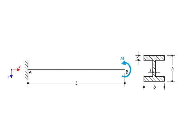
A cantilever of I-profile is supported on the left end and it is loaded by the torque M. The aim of this example is to compare the fixed support with the fork support and to investigate the behaviour of some representative quantities. The comparison with the solution by means of plates is also made. The verification example is based on the example introduced by Gensichen and Lumpe.
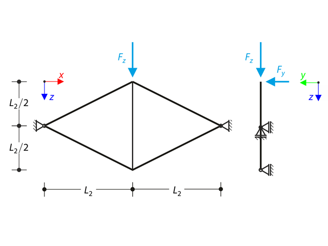
Planar truss consisting of four sloped members and one vertical member is loaded at the upper node by means of the vertical force Fz and out of plane force Fy. Assuming large deformation analysis and neglecting self-weight, determine the normal forces of the members and the out of plane displacement of the upper node uy. The verification example is based on the example introduced by Gensichen and Lumpe.

The model is based on the example 4 of [1]: Point-supported slab.
The flat slab of an office building with crack-sensitive lightweight walls is to be designed. Inner, border and corner panels are to be investigated. The columns and the flat slab are monolithically joined. The edge and corner columns are placed flush with the edge of the slab. The axes of the columns form a square grid. It is a rigid system (building stiffened with shear walls).
The office building has 5 floors with a floor height of 3.000 m. The environmental conditions to be assumed are defined as "closed interior spaces". There are predominantly static actions.
The focus of this example is to determine the slab moments and the required reinforcement above the columns under full load.
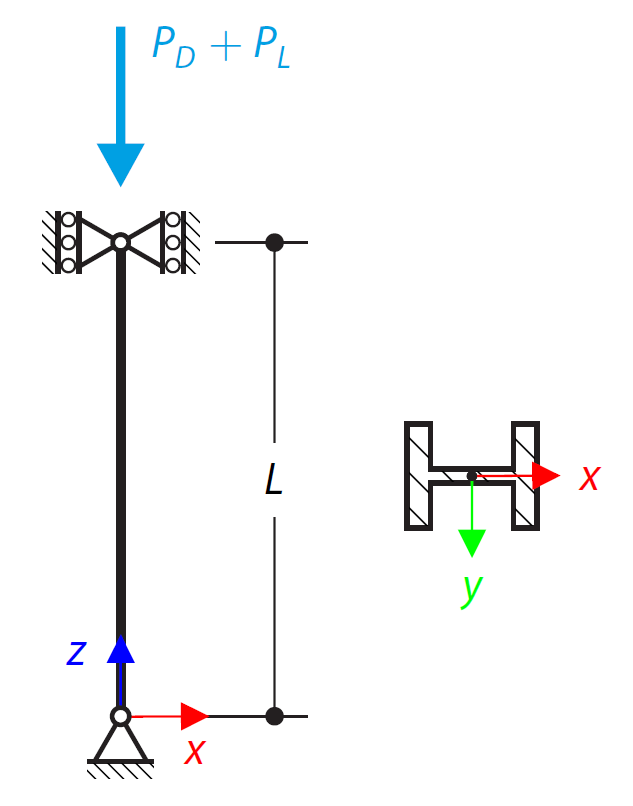
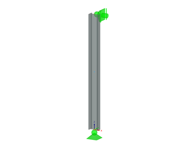
An ASTM A992 14×132 W-shaped column is loaded with the given axial compression forces. The column is pinned top and bottom in both axes. Determine whether the column is adequate to support the loading shown in Figure 1 based on LRFD and ASD.

Using AISC Manual tables, determine the available compressive and flexural strengths and whether the ASTM A992 W14x99 beam has sufficient available strength to support the axial forces and moments shown in Figure 1, obtained from a second-order analysis that includes P-𝛿 effects.
Determine the allowable axial compressive strength of a pinned 8-foot-long beam of various cross-sections made of Alloy 6061-T6 and laterally restrained to prevent buckling about its weak axis in accordance with the 2020 Aluminum Design Manual.
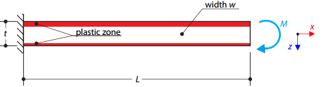
A cantilever is fully fixed on the left end and loaded by a bending moment on the right end. The material has different plastic strengths under tension and compression.
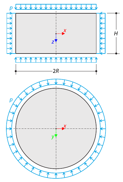
A cylinder made of elasto-plastic soil is subjected to triaxial test conditions. Neglecting the self-weight, the goal is to determine the limit vertical stress for shear stress failure. An initial hydrostatic stress of 100 kPa is considered.
A planar truss consisting of four sloped members and one vertical member is loaded at the upper node by means of a vertical force and an out-of-plane force. Assuming the large deformation analysis and neglecting the self-weight, determine the normal forces of the members and the out-of-plane displacement of the upper node.
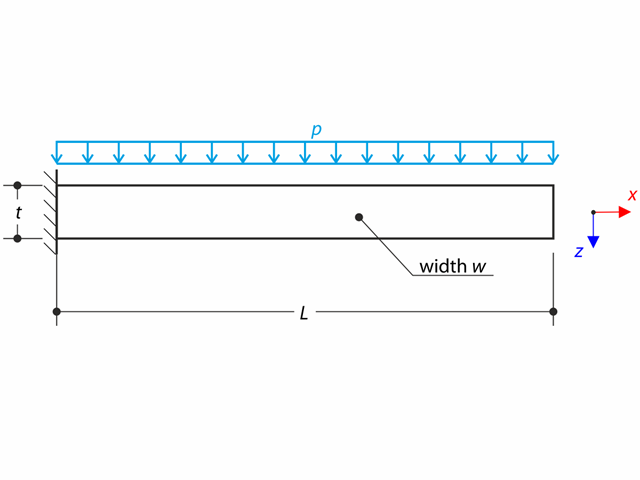
A thin plate is fully fixed on the left end and loaded by uniform pressure on the top surface. Determine the maximum deflection. The aim of this example is to show that a surface of the surface stiffness type Without Membrane Tension behaves linearly under bending.
Determine the allowable axial compressive strength of a pinned 8-foot-long beam of various cross-sections made of Alloy 6061-T6 and laterally restrained to prevent buckling about its weak axis in accordance with the 2020 Aluminum Design Manual.
Determine the allowable axial compressive strength of a pinned 8-foot-long beam of various cross-sections made of Alloy 6061-T6 and laterally restrained to prevent buckling about its weak axis in accordance with the 2015 Aluminum Design Manual.
Using AISC Manual tables, determine the available compressive and flexural strengths and whether the ASTM A992 W14x99 beam has sufficient available strength to support the axial forces and moments shown in Figure 1, obtained from a second-order analysis that includes P-𝛿 effects.
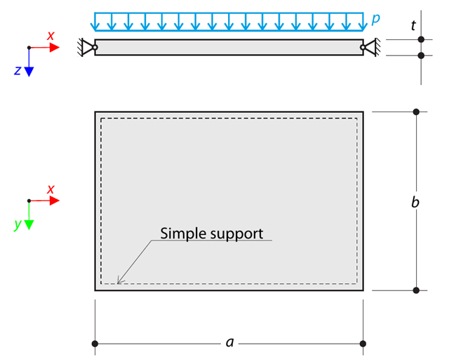
A thin rectangular orthotropic plate is simply supported and loaded by uniformly distributed pressure. The directions of axes x and y coincide with the principal directions. While neglecting self-weight, determine the maximum deflection of the plate.
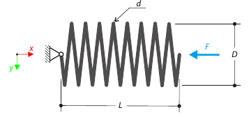
A closely coiled helical spring is loaded by a compression force. The spring has middle diameter D, wire diameter d, and it consists of i turns. The total length of the spring is L. Determine the total deflection of the spring for the member model and one‑turn deflection for the solid model.
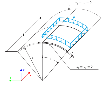
A shell roof structure under pressure load is modeled where the straight edges are free, while at the curved edges the y- and z‑translations are constrained. Neglecting self‑weight, compute the maximum (absolute) vertical deflection, and compare the results with COMSOL Multiphysics 4.3.
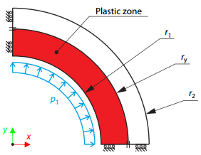
A thick-walled vessel is loaded by an inner pressure such that the vessel reaches an elastic-plastic state. While neglecting self‑weight, the analytical and numerical solutions for the radial position of the plastic zone border (under the Tresca hypothesis) are determined and compared.
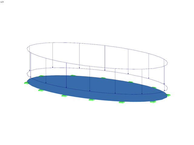
An elliptic plate with a clamped boundary is subjected to a uniformly distributed transverse load. Assuming the small deformation theory and neglecting the self‑weight, the maximum out‑of‑plane deflection of the plate is determined.